Introduction.
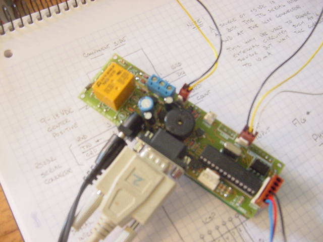
The TM #150 Module is a thermometer with a local LCD display. It also provides a thermostat function with a relay with a form C contact capable of switching 120/220 VAC. It also provides one 10-bit A/D conversion. It is intended as a standalone unit. However, an RS232 serial output is provided which may be used for logging temperature data.
The unit performs a temperature measurement using a single Dallas DS18S20 and displays the result in degrees F, the result of the 10-bit A/D conversion and the state of the relay and the configuration settings on the local LCD every 10 seconds.
The module may be simply configured using a PC COM Port to set the high and low temperature trip points, the thermostat polarity and the number of seconds between outputs on the RS232 port.
For example, setting T_HI to 80, T_LO to 75, POL to 1 and INT_SAMPLE to 60 will cause the relay to operate when the temperature rises above 80 degrees F and release when the temperature falls below 75. This might be used to operate a fan. Every 60 seconds, the temperature , the A/D measurement and the state of the relay is transmitted on the serial RS232 port. However, this logging feature is an extra. No interfacing PC is required for applications that do not require logging.
Setting the T_HI to 38, T_LO to 33, POL to 0 and INT_SAMPLE to 1800 will cause the relay to operate when the temperature falls below 33 degrees and release when the temperature rises above 38. This might be used as a freeze alarm. The temperature, the A/D value and the state of the relay are transmitted on the RS232 port every half hour (1800 secs).
Once the unit is configured, the information is saved to non-volatile memory or EEPROM and power may be removed without losing the configuration information. This feature permits the user to configure the TM #150 unit using a desk top PC and then installing the unit at the location where it is to be used.
However, the unit may be reconfigured using a PC COM port at any time and thus the unit might be used as a frost alarm during the fall and spring and reconfigured for use in a green house application during the summer.
Unlike many thermometers and thermostats where the temperature sensor must be located near the main unit, with this design, the DS18S20 temperature sensor may be located up to 200 feet from the unit using any twisted pair cable. No power is required at the remote point where the sensor is located.
Detailed Description.
Operational Mode.
Connect the temperature sensor to the connector marked "Dallas". This is near the relay terminal block.
Apply power.
A brief message will appear on the LCD.
The processor then checks to determine if this is the first time the unit was ever powered and if so, stores default values of T_HI, T_LO and POL of 80, 75 and 1, respectively. Thus, if the sensor is heated to 80 degrees or more, the relay will turn on and when the temperature falls below 75 degrees, it will release. The INT_SAMP is set to a default value of 60 seconds.
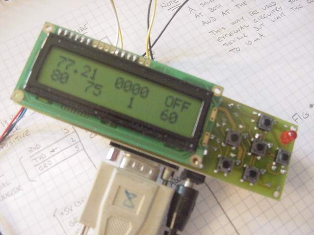
Every ten seconds, a temperature measurement is performed and displayed on Line 1. The A/D reading is displayed in field 2 and the state of the relay is displayed in field 3. The configuration settings, T_HI, T_LO, POL and INT_SAMP. are displayed on the second line, An LED is flashed each second to provide some feedback for a user too distant from the unit to read the LCD to assure the unit is operating.
Note that if a DS18S20 temperature sensor is not found or there is an error in communicating with the sensor, an error message is displayed in place of the temperature. The messages are device not found "DNF" or cyclic redundancy check failure "CRC".
Parameter INT_SAMP defines the interval between times when the values of the temperature, A/D converter and state of the relay are output on the RS232 serial port. This might be used for a data logging application
Using Hyperterm or a similar terminal emulator package, configure a PC COM Port as a direct connection, 9600 baud, no parity, no flow control. (Note that Hyperterm is supplied with many versions of Windows and may be downloaded from the internet at www.hilgraeve.com/htpe/ ).
You should view data of the form illustrated below.
71.23 0 FIf a device is not found or there is a communications error, the temperature is displayed as -99.00 or -88.00, respectively.
When the unit is powered up, a temperature value of -77.00 is sent to indicate to the logging program that there was a power interruption.
The second field is the A/D value and the third field is the state of the relay (on - 'N' or off - 'F').
Note that although the TM #150 unit has the capability of transmitting RS232 data, there is no need to use this capability. Its free and may be useful in some applications.
Configuration Setup.
As noted, the default values of T_HI, T_LO, POL, and SAMP_INT are 80, 75, 1 and 60.
To modify these, connect the unit to a PC COM port with a direct connection, 9600 baud, no parity and no flow control..
Momentarily, depress the pushbutton just below the LED and the TM #150 will toggle to the setup mode and display a menu of the following form;
	C - display Current programmed settings
	N - display New setting to be programmed
	H - set T_HI_new
	L - set T_LO_new
	P - set POL_new
	I - set sampling Interval

	T - measure Temperature
	A - perform an A/D conversion
	S - Save new settings
	Q - Quit and enter operational mode
Entering the character 'C will cause the current values stored in EEPROM to be displayed;
	Current Programmed Settings

	T_HI =  80
	T_LO =  75
	POL = 1
	INT_SAMPLE = 60
Entering the character 'N' will cause the proposed new configuration values to be displayed. Note that when the setup mode is first entered, the "new" values are the same as the "current" configuration values.
To set new values of T_HI, T_LO, POL or INT_SAMP, enter an 'H', 'L', 'P', or 'I'.
The unit will then prompt for the user to enter an appropriate value. The range of T_HI and T_LO is -55 to 199 degrees with no decimal point. POL must either be 0 or 1 and SAMP_INT must be in the range of 10 to 9999 seconds.
Note that at any time, the user may enter the 'N' command to examine the proposed new settings.
As a caveat, the user may perform a temperature measurement or perform an A/D conversion by entering the 'T' or 'A' commands.
The 'S' command saves the new settings to EEPROM. The user may wish to then use the 'C' command to verify they have been saved. Note that prior to saving, a check is performed to ascertain that T_HI is larger than T_LO, and if not the save is aborted. The user may then correct either T_HI or T_LO and then save.
The 'Q' command toggles the unit back to the operational mode. It is very important to note that the 'Q' command does not automatically save the new configuration settings. Rather, the new configuration must first be saved using the 'S' command. Otherwise, the configuration settings will remain unchanged.
Accidental Depression of the Setup Push Button.
A momentary depression of the pushbutton which is located under the LED will toggle the unit from the operational mode to the setup mode. Normally, the unit is returned to the operational mode using the 'Q' command. Of course, this is impossible without connecting the unit to a PC COM port which may be impractical.
If the unit is accidentally placed in the setup mode, simply remove power for a few moments to return the unit to the operational mode.
Miscellaneous Notes
1. The length of wire to the distant DS18S20 may be extended up to 200 feet using a single twisted pair.
2. The unit is supplied with a wall power unit. However, for portable or mobile operation, a DC source in the range of 8 to 15 VDC capable of providing 50 mA may be used. For example, a 12 VDC automobile battery in a vehicle is appropriate. However, a small nine volt transistor battery will not last very long. In many agricultural applications, the battery is 24 VDC and this may be a bit high for this unit. Contact me and I will provide a diode which may be placed in-line to drop the voltage at the TM #150 unit to nominally +12 VDC.
3. As with all monitoring devices, one must always weigh the risk of unit failure. I have great confidence in the design, but one should not rely on this design as the only device in controlling anything where there is a good deal of property. For example, using only one of these units to control fans in a hog barn would not be wise. This observation does not apply only to this unit, but any type of unit. One might consider greatly lowering the risk of failure by operating two units in parallel, but even then, one must consider the consequences of loosing power to both units.