Upgrade. (April 1, 05). On units shipping prior to Apr 1, '05, the interfaing Dallas devices which could be accommodated were the DS18S20 / DS18B20 / DS18B20-PAR / DS1822 Temperature sensor and the DS2438 Battery Monitor (commonly used for measuring relative humidity. On units shipped after Apr 1, '05, the DS2423 Dual 32-bit Counter and the DS2450 Quad A/D (12-bit) may also be accommodated on either of the two Dallas runs. This opens up a good many additional capabilites including measuring atmospheric pressure using a Motorola MPX4115 sensor interfaced with a DS2450, wind speed and rainfall measurement using the DS2423. Its pretty amazing how far one can push a 2K PIC!
Consider a typical response;
10 20 29AE 3.781 0.065 0.066 0.066
11 10 6A0B 35.56
12 10 9DD7 35.00
13 28 DB9C 34.50
14 22 5BFC 35.75
15 26 09CE 33.93 0.11 4.95
16 1D C827 00000003 0000001C
Note that a Dallas DS2450 (device code 10) was found. The four measurements follow the abbrevated serial number.
A DS2423 Dual Counter (device code 1D) was found. The two counts are in 32=bit hexadecimal. Thus, one counter is at 3 and the other is at 28 (16 + 12).
An upgrade PIC is available to anyone who has purchased the TM #128 prior to Apr 1, '05. It is $5.00. Please send me e-mail.
The firmware may be distinguished by noting the startup message. The message for the new units indicates "TM #128B". In addition, the upgrade design uses a PIC12F683. The prior designs used a PIC12C672.
The documentation which follows applies to the preupgrade TM #128. However, it is applicable to the new unit. The new unit simply adds the DS2423 and DS2450 interface capability.
Introduction.
The TM #128 is an assembled unit which interfaces with a PC COM port to perform measurements on any mix of Dallas DS18S20 and DS18B20 (DS1822) temperature sensors and DS2438 temperature and 10-bit A/D converters on each of two twisted pair runs. Up to sixteen devices with a maximum of 200 feet of twisted par cable may be accommodated on each of the two runs. In addition, a single TTL input is provided. The package includes an assembled printed circuit board, a nominal 12 VDC wall power unit, a six foot serial cable (DB9) and a single DS18B20. Additional DS18B20 temperature sensors and DS2438Z temperature and A/D sensors may be purchased separately.
The PCB is professionally fabricated.
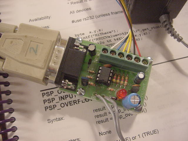
The module includes a female DB9 connector, RS232 level shift circuitry, an on-board 5 VDC supply, a Microchip PIC processor and a six conductor screw type terminal block. There are four holes on the PCB to permit the user to mount the module in a box or on a plate. Four one-half inch nylon spacers and associated 4-40 pan head screws are provided.
Note that this is the documentation for this module.
The module is 1.5 X 2.125 inches.
PC Interface using the Bloodshed Dev-C++ Compiler.
Interface with Windows using Liberty Basic.
Measuring RH and Dew Point using a Honeywell HIH-3610 and Dallas DS2438
Guarantee.
The intent is designing modules such as this is to involve my undergraduate students in meaningful design experiences, while at the same time providing useful low cost products for hobbyists and tinkerers.
In the spirit of this activity, I don't want people buying items that do not work for them or do not meet their expectations. Thus, this unit may be returned at any time for a full credit.
Detailed Description.
The PC or similar interfaces with the TM #128 module using 9600 baud, 8-bits, no Parity, either 1 or 2 stop bits, no flow control. Only the TX, RX and GRD leads are used. Note that a USB to RS232 serial converter may be used if you do not have a conventional COM Port.
On receipt of any character, the TM #128 performs a measurement sequence, beginning with the status of the TTL input and then finds each device on each of the two runs and performs the appropriate measurements. For example;
0
00 10 9DD7 26.12
01 10 BD53 26.12
02 28 3C2C 26.32
03 22 5BFC 26.43
10 10 0C26 27.18
11 10 0AD7 27.25
12 26 09CE 27.18 2.55 5.03
In the above, the state of the TTL input is a logic zero.
On Run 0 (first digit) the processor found two DS18S20s (code 10) and one DS18B20 (code 28) and one DS1822 (code 22) and the temperatures were 26.12, 26.12,26.32 and 26.43 degrees C.
On Run 1, three devices were found. Two were DS18S20s (code 10) and the temperatures were 27.18 and 27.25 degrees C. One DS2438Z (code 26) was found. The temperature was 27.18 degrees C and the voltages on the DS2438 Vad and Vdd inputs are 2.55 and 5.03 VDC, respectively.
The measurement time associated with each device is nominally one second.
Note as each device is found, it is assigned an identity consisting of the run (0 or 1) and a sequential number in the range of 0 - F. This sequential number is simply a running number which is assigned as each device is found.
The second field identifies the type of device; DS18S20 - Code 10, DS1822 - Code 22, DS18B20 - Code 28 and DS2438 - Code 26. Field three is a unique 16-bit identifier for the device. Note that the actual Dallas ID consists of 48-bits and in the above, only 16 are being used. However, the sixteen bits provides for 65,535 combinations and I seriously doubt anyone will find a duplication in their system.
Note that if you modify your system, the sequential number in the first field associated with a particular sensor will probably change. The order that each device is found is in no way related to its physical location on the twisted pair rail. Modifying your system may be inadvertent. If you rely on this sequential number and the beagle eats the sensor in the living room, you might actually be measuring the temperature in the freezer and believe it to be that in the living room. This is, of course, an extreme case, but hopefully it drives home the idea of using the serial number in field three to specifically identify which temperature is associated with each physical sensor.
If there is a communications error performing a measurement, the value -88.88 is displayed. If this occurs frequently, it is a red flag that there is too much cable on the run. Too much cable (actually, the capacitance associated with the cable) will cause intermittent communication problems with all devices on the run, and not simply those sensors which are most distant from the TM #128 unit.
If no devices are found on a run, no data is returned to the PC or similar for that run. For example;
0
10 10 0C26 27.18
11 10 0AD7 27.25
12 26 09CE 27.18 2.55 5.03
Indeed, there may be no devices on Run 0. Or, perhaps, there is a "stuck at ground" fault on the run or there is a break in the cable.
If no devices are found on either run, only the state of the TTL input will be displayed.
0This may be helpful in initially configuring your system as it verifies that your PC or similar and the TM #128 are communicating with one another.
The DS18S20, DS18B20 and DS1822 operate in the parasitic power mode. That is, the power required to operate the sensor is obtained from the signal line. Thus, only the DQ and GRD leads are connected to these devices.
However, with DS2438, a power source in the range of 2.5 to 10.0 VDC capable of providing 100 uA is required at Vdd. This may be locally supplied, or a source of +5 VDC may be run from the TM #128 unit. In some situations, you may have a voltage source having a low internal impedance and in the range of 2.5 to 10.0 VDC that you wish to measure and this may be used to supply Vdd. In this case, the DS2438 is actually performing two useful 10-bit A/D conversions, one on Vad and the other on Vdd.
In today's world, we have inexpensive CAT 5 low capacitance cable with four twisted pairs. Use one pair for DQ and GRD for all devices on the run. Use another pair to provide power at Vdd for the DS2438. Add a 0.01 to 0.1 ceramic capacitor between Vdd and GRD at the DS2438.
One might offer that Dallas sure should know the limitations of their own products. In large companies, different organizations follow their own path and one group developed a weather system that in some cases threw worst case theory to the wind. A weather system might well help advertise Dallas products and I assume this is why its development was justified. But, notice that Dallas no longer offers this. No company can stand behind a flawed product.
The range of the temperatures at which operation is assured for the DS18S20, DS18B20 and DS2438 is -40 to 85 degrees C. The unit provides a resolution of 0.03125 degrees C for the DS18S20 and DS2438 and 0.0625 resolution for the DS18B20 and DS1822. Please refer to the data sheets at Dallas Semiconductor for absolute accuracy over the full temperature range. (Note that the DS1822 is functionally the same as the DS18B20. In fact, the DS1822 was designed as an economy version of the DS18B20 at some sacrifice in accuracy. However, I have found the inferior DS1822 costs just about the same as the DS18B20).
The DS2438 A/D converter is a ten bit A/D and the device uses an internal band gap reference such that the readings are reported in VDC over the range of 0.0 to 10.23 VDC.
Setup and Test.
The unit is shipped with small lengths of wire of various colors attached to the terminal block to aid in identifying the functions.
When making or changing connections to the terminal block it is suggested that the unit be powered down.
Connect the module to a PC COM Port using the DB9 serial cable.
Use a terminal emulator such as HyperTerm which is provided as a free accessory with Windows to establish a a direct connection to the COM port at 9600 baud, eight data bits, no parity, and no flow control.
Power the unit by plugging in the wall power unit. Observe the power on LED.
When the unit boots either by applying power or resetting the processor via the blue lead on the terminal block, a brief screen message will be sent to the PC which includes the date the firmware was last modified.
Type any character and observe the state of the TTL input. You might connect the white lead (TTL input) to +5 VDC and observe the input is read as a logic one. Repeat with the white lead connected to GRD and verify a logic zero.
As you add sensors to the the twisted pair runs, it is suggested that you add them one at a time. Type a character and verify the measurements.
Notes.
1. This module is distributed with a programmed PIC which is code protected. The source code written in PIC C from is available for $1500.00.
2. The firmware associated with this design is a rework of many of my other serial measurement modules which also use a PIC12C672 However, the PICs are not interchangeable.
3. The processor which was used in this device does not have a hardware UART. Thus, while the processor is performing a task such as performing a temperature measurement sequence, the processor will not see a character which is sent by the PC to initiate a new sequence until the current sequence is completed.. The interfacing PC or similar should wait until the current measurement sequence has been completed.
3. This design uses a calibrated RC clock inside the PIC microcontroller (as opposed to an external crystal or resonator). In reviewing the specifications, this appears more than sufficiently accurate to perform the timing involved in communicating with the PC. If it isn't, this will be apparent with all kinds of control characters appearing on your terminal. By all means, if this happens, return it to me. I honestly do not feel this will be a problem.
4. Use the +5 VDC output on the terminal block judiciously. The current should not exceed 50 mA. This may be used to power the remotely located DS2438s and a a small amount of peripheral circuitry.
5. Several years ago, Dallas marketed a DS1820 in a PR35 package (an elongated TO-92 transistor package). They then replaced this with the DS18S20 in a TO-92 package. However, for whatever reason, Dallas marks these parts as DS1820. The TM #128 design is compatible with both. They are both code 10 devices.
6. Note that my 200 foot recommendation is 200 feet total for each run. Thus you might have a single 200 foot twisted pair or two 100 foot pairs or five 40 foot pairs in a star configuration. I may be very conservative with this 200 feet. Using low capacitance CAT 5 cable, you may well find you can go much further. But, once you begin to receive communication errors (-88.88), you have probably stretched the cable too far.
Ordering Information. Please order as Temperature Module TM #128.
White - TTL input
Blue - Reset.  Momentarily GRD to reset the processor.  This should not normally be necessary.
Yellow - DQ lead for one Dallas twisted pair run
Yellow - DQ lead for the other run
Black - Ground
Red - +5 VDC (to possibly power remotely located DS2438 devices.)