Introduction.
The ADC #180 is an assembled unit which interfaces with a PC COM port to perform measurements on each of eight 10-bit analog to digital converters.
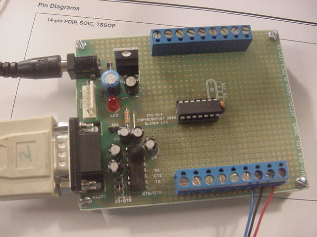
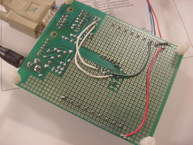
The PCB was professionally fabricated, but includes a small amount of hand wiring. (See photos). The dimensions of the module are 3.9 x 3.15 inches.
The module includes a female DB9 connector, RS232 level shift circuitry, an on-board 5 VDC supply, a Microchip PIC processor and two 9-conductor screw type terminal blocks. There are four holes on the PCB to permit the user to mount the module in a box or on a plate. Four one-half inch nylon spacers and associated 4-40 pan head screws are provided.
A six foot nine conductor DB9 serial cable and a 120 VAC to 9 VDC wall power unit is provided.
The user may opt to wire circuitry on the circuit board or interface with external sensors using the screw type terminal blocks.
I have wired +5 VDC, GRD and /RESET to one of the terminal blocks.
Momentarily ground the /RESET (blue) to reset the processor. This should not normally be necessary.
The +5 VDC may be used to power external circuitry. However, the current should be limited to 200 mA.
Detailed Description.
The PC or similar interfaces with the ADC #180 module using 9600 baud, 8-bits, no parity, either 1 or 2 stop bits, no flow control. Only the TX, RX and GRD leads are used. Note that a USB to RS232 serial converter may be used if you do not have a conventional COM Port.
On receipt of any character, the ADC #180 performs analog to digital conversions on each of the eight channels and returns the data to the PC or similar in decimal format;
 446  479  425  511
 462  427  790  708
The processor actually performs 32 conversions on each channel and then averages the result.
Each measurement is in the range of 0 to 1023. The output of the on-board 7805 (very close to 5.00 VDC) is Vref+ and ground is Vref-. Thus, a reading of 425 is interpretted as 425 / 1024 * 5.0 or 2.075 VDC.