Sept, '09. This item has been discontinued. The TM #128 is similar in function.
Introduction.
This is an assembled unit which interfaces with a PC COM port and provides the capability of measuring two analog voltages in the range of 0.0 to 5.0 VDC with a resolution of 5 mV. It also provides the capability of measuring the temperatures at each DS18S20 on a single twisted pair. It includes an assembled printed circuit board, a 12 VDC wall power unit, a six foot serial cable (DB9) and a single DS18S20. Additional DS18S20s may be purchased separately.
The two 10-bit analog to digital converters use the onboard +5 VDC as Vref.
In theory, up to 256 DS18S20 temperature sensors may be accommodated on the single twisted pair. However, the limiting factor is the capacitance and my suggestion is up to sixteen DS18S20 devices on a maximum of 200 feet of twisted pair cable.
The PCB is professionally fabricated.
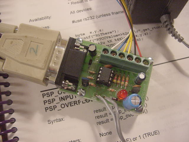
The module includes a female DB9 connector, RS232 level shift circuitry, an on-board 5 VDC supply, a Microchip PIC processor and a six conductor screw type terminal block. There are four holes on the PCB to permit the user to mount the module in a box or on a plate. Four one-half inch spacers and associated 4-40 pan head screws are provided.
Note that this is the documentation for this module. A figure is also shipped with the unit.
The module is 1.5 X 2.125 inches.
Guarantee.
The intent is designing modules such as this is to involve my undergraduate students in meaningful design experiences, while at the same time providing useful low cost products for hobbyists and tinkerers.
In the spirit of this activity, I don't want people buying items that do not work for them or do not meaat their expectations. Thus, this unit may be returned at any time for a full credit.
Detailed Description.
The PC interfaces with the temperature measurement and dual A/D module using 9600 baud, 8-bits, no Parity, either 1 or 2 stop bits, no flow control.
When idle, the PC TX lead is low, which may be anything from ground to minus 12 VDC and the processor is idle.
When a character is sent by the PC, the PC TX lead momentarily goes high which causes the PIC to initiate a complete measurement sequence.
The format of the returned data is three digit hexadecimal in the range of 0x000 to 0x3ff;
31C 07ANote that the two measurements are separated by a single space and the line is terminated by a new line consisting a CR and LF.
If no DS18S20s are found, no data is returned to the PC.
Each temperature measurement requires nominally one second.
The format of the returned data is;
DD TTT.T SSSSSSSS SSSSSSSSwhere
DD a sequential hexadecimal number in the range of 00 - FF.
TTT.T is the temperature result in degrees C.
SSSSSSSS SSSSSSSSS is the unique 64-bit serial number of the DS18S20 expressed in hexadecimal
For example;
00 27.0 10D6F33A 00000036
01 26.5 10773B3B 000000CE
02 -5.5  etc
03 105.0 etc
Note that in this example, four devices were found on the single twisted pair.
Note that fields are delimited by single spaces and the line is terminated by a new line consisting a CR and LF.
The range of the temperature is -55.00 to 125.00 degrees C. The unit provides a resolution of 0.5 degrees C. Please refer to the DS18S20 data sheet at Dallas Semiconductor for absolute accuracy over the full temperature range.
The serial numbers of the devices are provided to permit the user to ascertain which sensor is which. Note that the two digit device number DD is simply a running number beginning at 00 which is assigned as each device is found using a binary search on each of the twisted pair runs.
Thus, 00 might correspond to a DS18S20 in your PC, 01 to the living room, 02 to the freezer. Assume you then add one on a cold water pipe in the basement. You may well find 00 is still your PC, but 01 is now the water pipe, 02 is the living room and 03 in the freezer.
However, note that once a system is in place, 00 will always be the PC, 01 the water pipe, etc. But if your cat pulls off the sensor in the living room, 02 will then be the freezer.
If you don't wish to use the serial number information, you might consider initially connecting the sensors on a breadboard and use your finger to determine which device is 00, which is 01, etc and then label each of the sensors and then install them with 00 in the PC, 01 in the living room, etc.
Note that all DS1820 devices are operated in the parasitic power mode (the DS1820s use the signal lead for power) and thus a single twisted pair may be multipled from one device to the next.
The PIC is theoretically capable of finding and measuring the temperature of each of 281,000,000,000,000 devices on the single twisted pair run. However, the limiting factor is the capacitance of the cable and the capacitance of each DS1820. My guesstimate is that 16 devices on a total of 200 feet of twisted pair is realistic. Note that the use of the parasitic power mode does not limit the amount of cabling nor the number of devices.
Setup and Test.
The unit is shipped with small lengths of wire of various colors connected to the screw type terminal block to aid in identifying the functions.
GP5 (Yellow) DQ (to DS18S20s)
GP4 (White) ADC1
GP2 (White) ADC0
GP3 (Blue) Reset (ground to reset processor)
+5 VDC (Red) +5 VDC (output)
GRD (Black) GRD
When making or changing connections to the terminal block it is suggested that the unit be powered down
To test each A/D, connect two 10K resistors, provided with the package, in series between +5 VDC (term 2) and GRD (term 1). Thus, the voltage at the center node will be nominally 2.5 VDC. Connect one of the A/D inputs (White) to this node.
+5 VDC (Red) ----  10K ------ 10K ------- GRD (Black)
                             |
                             |

                             To ADC (White)
Connect a DS18S20 to the twisted pair as shown;
Screw Terminal Block		DS18S20

GP5 DQ (Yellow) ----------- DQ (term 2) --------------- To other DS18S20 devices
GRD (Black) --------------- GRD (terms 1 and 3) ------- To other DS18S20 devices
Connect the module to a PC COM Port using the DB9 serial cable.
Use a terminal emulator such as HyperTerm which is provided as a free accessory with Windows to establish a a direct connection to the COM port at 9600 baud, eight data bits, no parity, and no flow control.
Power the unit by plugging in the wall power unit. Observe the power on LED.
On boot (application of power), the module will send not send an advertisement to the PC. There simply was not enough program memory. Although I have not observed it, there may be a few bytes of garbage on power on.
Type any character. This should first perform A/D measurements on each of the two 10-bit A/D channels and then initiate a temperature measurement sequence. You should view the results on the PC terminal in the format illustrated above.
Note that the application of power will cause the PIC to boot and it should never be necessary to "boot" the processor again. However, just in case, access to RESET is provided at terminal 3 of the screw type block. The processor may be reset by momentarily connecting this to ground (terminal 3 to terminal 1).
Notes.
1. This module is distributed with a programmed PIC which is code protected. The source code written in PIC C from is available for $1000.00.
2. The firmware associated with this design is a rework of our "Serial Temperature Measurement System (8-pin DIP) Kit". However, the PICs are not interchangeable.
3. This design uses a calibrated RC clock inside the PIC microcontroller (as opposed to an external crystal or resonator). In reviewing the specifications, this appears more than sufficiently accurate to perform the timing involved in communicating with the PC. If it isn't, this will be apparent with all kinds of control characters appearing on your terminal. By all means, return it to me. I honestly do not feel this will be a problem
4. A source of +5 VDC is provided on terminal 2. This should be used judiously and the current should not exceed 50 mA. This may be used to power a small amount of peripheral circuitry. Note that this is the Vref used by the A/Ds which may be of use in many applications.
5. Several years ago, Dallas marketed a DS1820 in a PR35 package (an elongated TO-92 transistor). They then replaced this with the DS18S20 in a TO-92 package. However, for whatever reason, Dallas marks these parts as DS1820. This design is compatible with both. Both the old and the new may be accommodated on twisted pair.
6. The limiting factor on the amount of cable and the number of DS18S20 devices which can be accommodated is the capacitance associated with the cable and to a much lesser extent, that associated with the devices. In all probability, you can exceed my 200 foot recommendation. However, recognize that at some point, the measurements will fail and this will include both DS18S20s which are close to and far from the module.
Note that my 200 foot recommendation is 200 feet total. Thus you might have a single 200 foot twisted pair or two 100 foot pairs or five 40 foot pairs in a star configuration.