Overview.
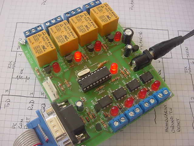
This is a fully assembled unit that is controlled by a Basic Stamp 2, BasicX BX24 or PICAXE or similar (2400 baud, 8 data bit, no parity, no flow control).
It provides four form C relays (15A / 120 VAC, 10A / 240 VAC, 15 A / 24 VDC) with a three position screw type connector for each relay. An LED is provided for each relay such that one can visually observe the state of the relay.
Further, it provides four optoisolators, each with a two position screw type connector and LED.
The serial interface will accommodate TTL (5.0 and GRD) levels. That is, teh BS2, BX24 or PICAXE may be directly interfaced with the IO Module with no intermediate circuitry.
The PCB is professionally fabricated.
The module includes a female DB9 connector, an on-board 5 VDC supply, a Microchip PIC processor, four relays and associated driver transistors and LEDs and terminal blocks, four 4N37 optoisolators and associated LEDs and terminal blocks.
A separate LED is provided which blips one time nominally every ten seconds when idle to indicate the unit is alive and blips multiple times when a command is received from the controlling.
The unit is mounted on four 0.5 inch nylon standoffs.
The unit includes a coaxial power connector which will accommodate a 9 - 12VDC (2.1mmID x 5.5mmOD female center positive) wall power unit and compatible 120 VAC wall power unit.
A DB9M connector with three leads to interface with the controlling processor is also included. The leads are about 24 inches long.
Guarantee.
The intent is designing modules such as this is to involve my undergraduate students in meaningful design experiences, while at the same time providing useful low cost products for hobbyists and tinkerers.
In the spirit of this activity, I don't want people buying items that do not work for them or do not meet their expectations. Thus, this unit may be returned at any time for a full credit.
Detailed Description.
The relays are identified as 1, 2, 3 and 4. Each may be independently operated by issuing either an "N" (oN) or "F" (oFf) command to the IO module. Note that a 0 operates or releases all four relays. The command is to be followed with a new line character, ASCII 10 and 13.
For example;
	N1		' operate relay 1
	N3		' operate relay 2
	F1		' turn off relay 1
	N4		' turn on relay 4
	F0		' turn off all relays
	N0		' turn on all relays
In addition, each second, the IO module reads the state of the relays and the state of the optoisolator inputs and sends this to the controlling processor at 2400 baud. The form of the command is the character 'X' followed by the state of the four relay represented by a single hexadecimal digit followed the the state of the four optoisolator inputs. This is followed by a new line character, ASCII 10 and 13.
For example;
X0FThe character 'X' is intended as a "framing byte". That is, the controlling processor should read the two bytes immediately following this byte. The 0 indicates the state of the relays is 0000 or all off. The 'F' indicates the state of the optoisolators is 1111. This indicates all optoisolators are off.
X8E The 8 or 1000 binary indicates Relay 4 is operated and the others are released. The E or 1110 indicates Optoisolator 0 is turned on.
Note that this status information is sent to the processor every second. This is done to accommodate the PICAXE. If the PICAXE should miss one transmission, the PICAXE will not hang in the SerIn command as the data will be repeated in another second.
' Relay.BS2  (Basic Stamp 2)
'
' Illustrates an interface with the Serial IO Module
'
' Releases all relay using the "F0" command.
'
' Then operates in a continual loop, turning on relay 1, relay 2
' relay 3 and relay 4.  After each operation, the relay states and
' the optoisolator states are read and displayed using the Debug
' command.
'
' Relays are then successively turned off.
'
'
'  Basic Stamp 2		Serial IO Module
'
'  P1 (term 6)---------------------> term 3
'  P0 (term 5) <----------- term 2
'  GRD -------------------------- term 5

'
' Copyright, Peter H. Anderson, Baltimore, MD, Oct 8, '06


    BaudMode  Con      396 + $4000      '2400 Inverted

    RelayNum Var Byte
    RelayStates Var Byte
    OptoInputStates Var Byte
    N Var Byte
    TempVar Var Byte
    Dummy Var Byte


    Dir0 = 0  ' serial input
    Dir1 = 1  ' serial output.
    Out1 = 0  ' be sure SerOut pin is stable at zero
    Pause 1000
    SerOut 1, BaudMode, 10, ["F0", 10, 13]

Top:
    For RelayNum = 1 to 4
        SerOut 1, BaudMode, 10, ["N", Dec1 RelayNum, 10, 13]
Top1:
        Pause 100
        Serin 0, BaudMode, 1500, TimeOut, [Dummy, RelayStates, OptoInputStates]
        ' Debug Dummy, RelayStates, OptoInputStates, CR
        If Dummy <> "X" Then Top1

        GoSub DisplayRelayStates
        GoSub DisplayOptoStates
        Pause 2000
    Next

    For RelayNum = 1 to 4
        SerOut 1, BaudMode, 10, ["F", Dec1 RelayNum, 10, 13]
Top2:
        Pause 100
        Serin 0, BaudMode, 1500, TimeOut, [Dummy, RelayStates, OptoInputStates]
        ' Debug Dummy, RelayStates, OptoInputStates, CR
        If Dummy <> "X" Then Top2

        GoSub DisplayRelayStates
        GoSub DisplayOptoStates

        Pause 2000
    Next
    Goto Top

TimeOut:
    Debug "Timeout Error", CR
    Goto Top

DisplayRelayStates:

    TempVar = RelayStates
    GoSub CharToNum
    Debug "Relay States - ", Dec TempVar.bit3, " "
    Debug Dec TempVar.bit2, " ", Dec TempVar.bit1, " ", Dec TempVar.bit0, CR
    Return

DisplayOptoStates:

    TempVar = OptoInputStates
    GoSub CharToNum
    Debug "Opto Input States - ", Dec TempVar.bit3, " "
    Debug Dec TempVar.bit2, " ", Dec TempVar.bit1, " ", Dec TempVar.bit0, CR
    Return

CharToNum:
    If TempVar < 10 Then Numeric
    ' otherwise, it is "A - F"
    TempVar = TempVar - "A" + 10
    Return
Numeric:
    TempVar = TempVar - "0"
    Return
' Relay.Bas  (PICAXE-18X)
'
' Illustrates an interface with the PICAXE Serial IO Module
'
' Releases all relay using the "F0" command.
'
' Then operates in a continual loop, turning on relay 1, relay 2
' relay 3 and relay 4.  After each operation, the relay states and
' the optoisolator states are read and displayed using the SerTxD
' command.
'
' Relays are then successively turned off.
'
'
'  PICAXE-18X				Serial IO Module
'
'  Output 7 (term 13) ----------> term 3
'  Input 1 (term 18) <----------- term 2
'  GRD -------------------------- term 5
'
' copyright, P H Anderson, Baltimore, MD, Oct 8, '06

   Symbol MaskByte = b0
   Symbol RelayNum = b1
   Symbol RelayStates = b2
   Symbol OptoInputStates = b3
   Symbol N = b4
   Symbol TempVar = b5

   Pin7 = 0 ' be sure Serial Out is stabilized at a logic zero
   Pause 2000
   SerOut 7, N2400, ("F0", 10, 13)
   Pause 1000

Top:

   For N = 1 to 4  ' turn on each relay in turn

      SerOut 7, N2400, ("N", #N,10, 13)
      Pause 100
      Serin 1, N2400, ("X"), RelayStates, OptoInputStates

      GoSub DisplayRelayStates
      GoSub DisplayOptoStates
      Pause 2000
   Next

   For N = 1 to 4  ' turn off each relay in turn

      SerOut 7, N2400, ("F", #N, 10, 13)

      Serin 1, N2400, ("X"), RelayStates, OptoInputStates

      GoSub DisplayRelayStates
      GoSub DisplayOptoStates
      Pause 2000
   Next

   Goto Top ' run in continual loop


DisplayRelayStates:

      TempVar = RelayStates
      GoSub CharToNum
      MaskByte = TempVar
      SerTxD ("Relay States - ", #bit3, " ", #bit2, " ", #bit1, " ", #bit0, 10, 13)
      Return

DisplayOptoStates:

      TempVar = OptoInputStates
      GoSub CharToNum
      MaskByte = TempVar
      SerTxD ("Opto States - ", #bit3, " ", #bit2, " ", #bit1, " ", #bit0, 10, 13)
      Return

CharToNum:
      If TempVar < 10 Then Numeric
      ' otherwise, it is "A - F"
      TempVar = TempVar - 65 + 10
      Return
Numeric:
      TempVar = TempVar - 48
      Return