Assembly Instructions for the Protoboard for an 18-terminal PICAXE
This provides assembly instructions for the Protoboard for an 18-terminal PICAXE. The silkscreen on the PCB is very good and you should have little trouble quickly and accurately assembing this high qualtity board.
In the following, I have also identified the Jameco part number for those who wish to purchase only the PCB.
I suggest mounting all low profile components first, followed by the electrolytic capacitors, power jack, D-sub connector, and finally the 7805 regulstor. This will assure that the board will sit reasonably flat during assembly and also assure a minimum of difficult in mounting some of the smaller components.
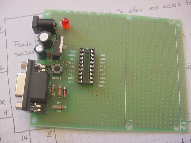
- R1, 10K, (brown, black, orange), 1/4W, Jameco 29911. Note that this resistor should be mounted vertically. See the photo. This resistor is adjacent to the 18-terminal socket.
- R2, 330, (orange, orange, brown), 1/4W, Jameco 30867.
- R3, 220, (red, red, brown), 1/4W, Jameco 30470.
- R4, 22K, (red, red, orange), 1/4W, Jameco 30453.
- R5, 10K, (brown, black, orange), 1/4W, Jameco 29911.
- D1, 1N4004, Jameo 35991. Place such that the band on the diode is aligned with the silkscreen on the PCB.
- Z, 1N5818, Jameco 177957. This diode is located adjacent to R4. Align such that the band on the diode is aligned with the silkscreen on the PCB.
- RESET, switch, pushbutton, Jameco 119010.
- LED, Jameco 94511. Align such that flat on LED is aligned with the silkscreen.
- IC1, 18-terminal socket, Jameco 112230. Align notch on the end of the socket with the silkscreen.
- C1, 220 uF, 25 VDC, Jameco 30497. Align the minus on the capacitor with the silkscreen.
- C2, 100 uF, 25 VDC, Jameco 93762. Align such that plus side of capacitor agrees with plus sign on the silkscreen.
- C3, 0.01 uF, ceramic, Jameco 15230.
- PWR, coaxial power connector jack, 2.1 mm center, Jameco 101178. After placing, bend the tabs to hold the jack in place while soldering.
- CON1, 9-term D-sub connector, Jameco 104951. Placing this requires alignment of all 9-terminals with the holes on the PCB. Check to be sure none of the terminals are bent. Place and gently turn back and forth, while exerting minimal pressure until the connector drops into place.